The Sigaba, how it works
The Sigaba Home Page
- Introduction
- Description (how it works),
This Page. - Procedures
- Simulators
- Cryptanalysis
- Challenges
Introduction
The Sigaba is an electromechanical cipher machine whose essential components are rotors.
The rotor concept is revolutionary. It easily allows electrical circuits to be swapped and, what is more, to change this permutation for each encrypted letter if the rotor turns, hence its name (see the concept of Rotor). Most cipher machines, including the Enigma, are machines equipped with rotors.
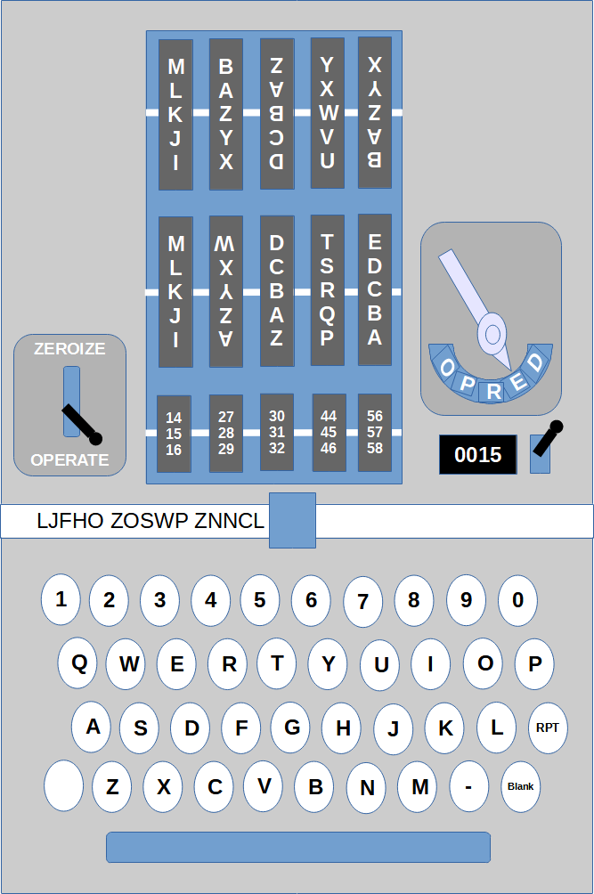 |
Description of Figure 1: At the top, we see the basket that contains the rotors (csp-887). We can partially see the rotors (which allows us to put them at the message key). We can see the external key at the benchmark: KZBWZ, KYBRC, 15-28-31-45-57. The five rotors at the top correspond to the encryption rotors. The third and fifth are reversed. The five middle rotors correspond to the control rotors. The second is reversed. The last five rotors correspond to the index rotors. On the right of the rotors there is the master switch which allows you to position the machine in different modes: power-off (O), plain (P), Reset (R), Encrypt (E) and Decrypt (D) modes. Below there is the counter and a small lever to reset it. On the left side of the rotors, there is the switch which allows you to switch from Zeroize to Operate mode. Below there is the print head which prints on a strip of paper. Below there is the keyboard.On the right, we can see the Dash, Repeat (RPT) and Blank keys. On the left, a key is empty: it is the dummy-key.
The components (in broad terms)
- A user interface:
- A typewriter keyboard.
- A printer system that prints on a strip of paper.
- A master switch which allows the choice of the mode of use of the machine, mainly encryption and decryption modes.
- A switch that allows you to switch from Zeroize mode to Operate mode
- A counter that is incremented for each letter encrypted or decrypted. A switch allows you to reset it.
- The rotors: we can see the external key (start position of rotors)
It is possible to change the initial position of the rotors and therefore the message key. If we use the Navy indicator system, the keyboard is sufficient to position the message key.
-
An equipment that permits encryption or decryption.
This equipment is itself
made up of two components:
- A part which is made up of 5 rotors used in cascade and which allows the encryption (or decryption) of a single character. This part is directly inspired by Hebern's 5-rotor cipher machine (see ...)
- The Stepping Maze. It is an electrical circuit which powers the relays which cause the stepping of the encryption rotors.
The rotors and the basket that houses them
The rotors are the essential components of a Sigaba encryption machine. There are 15 rotors. These rotors are divided into three groups:
- The 5 encryption rotors.
- The 5 control rotors.
- The 5 index rotors.
The rotors are housed in a removable basket (CSP-887). You must remove the basket if you want to position the rotors in the order and orientation indicated by the daily key.
This basket makes it easy to change the base key if you want to encrypt a message for another encryption network (see procedures). The ability to quickly remove the rotors permit too to throw them overboard in the event of a boarding of the US ship equiped with a Sigaba.
 |
The Stepping Maze – the concept
The Stepping Maze constitutes the great innovation of this machine. This invention (in broad terms) was made by Frank Rowlett.
The main flaw of the first cipher machines, including the Hebern 5-rotor machine of 1924 (but also the Enigma) is the regular stepping of the rotors (like an odometer). The objective of the Stepping Maze is to cause the encryption rotors to stepping as closely as possible to random mouvement.
Thanks to the Stepping Maze, at least one rotor steps, but several can step. This was already the case with the Hebern 5-rotor machine from 1934, but thanks to Rowlett's invention, it is almost impossible to predict which rotors will step.
 |
The Stepping Maze – implementation
General vision
Rowlett's big idea is to use rotors to generate electrical currents that power the relays causing the encryption rotors to step. The control rotors (those which control the stepping of the encryption rotors) step regularly in a manner similar to the encryption rotors of the Hebern 5-rotor machine of 1924. They step after each encrypted letter.
The components
- The electrical impulse generator. It energizes several cables (for example 4) which will be permuted by the control rotors. These cables are fixed relative to the rotors.
-
The control rotors (this is the essential element). There are 5 of them. They
step regularly after each encrypted (or deciphered) letter. These rotors
have 26 contacts and are therefore interchangeable with the encryption rotors.
One day, rotor 02 can be used as the 3rd encryption rotor and the next day
(depending on the key of the day), be used as the 5th control rotor.
Note: as with the Hebern Rotor machine, a rotor can be positioned in the normal direction or in the inverted direction (the index letters are upside down) (see Figure 1). This possibility (absent in the Enigma) enormously increases the key space.
- Index rotors. It’s an invention of a Navy cryptologist (Lt Cmdr Donald J. Seiler). They make it very easy to swap the cables which lead to the relays controlling the stepping of the encryption rotors. In a first version of the Sigaba, a 10-pin plugboard fulfilled this role. There are 5 index rotors which each have 10 contacts. They do not step during encryption.
- The electrical circuit that connects the output of the last control rotor to the first index rotor. This circuit mixes several cables because there are 26 contacts for a control rotor and only 10 contacts for the index rotors. At most, there will be as many lines energized as there are cables energized by the generator.
- The electrical circuit that connects the output of the last index rotor to the relays that control the stepping of the encryption rotors. Here too, the circuit mixes several cables because an index rotor has 10 contacts and there are only 5 relays. Here again, the number of relays energized (and therefore the number of rotors which step) is limited to the number of cables energized by the generator. In the first version of the Sigaba, there were only 4 cables energized by the generator and therefore there was at least one relay energized and therefore at least one rotor which step and at most 4 relays energized and therefore at most 4 rotors which moved.
 |
 |
The different operating modes
The master switch allows you to choose the operating mode:
- Master switch in Power-off mode (O)
In this mode, the machine is not supplied with electrical current and therefore does not operate. In this mode you can remove/replace the basket (CSP-887) which contains the rotors (encryption, controls and index ones). When the basket is out of the machine, you can remove the rotors and put them in the order indicated by the key of the day (see procedure). We can very quickly replace the set of rotors used (for example) by the Army by the set of rotors used for Army-Navy inter armed forces dialogue.
- Master switch in Plain mode (P)
In this mode, the Sigaba can be used as a simple typewriter. It is very useful for printing message headers and trailers (indicators, date, time, security level, etc.). The Sigaba prints the typed characters as they are: the letters of the alphabet, the numbers, the minus (dash), the space. You can use the RPT (repeat) key which allows you to repeat a character.
Notes:
- In this mode, the rotors do not step.
- The RPT (repeat) key only works if it is held down BEFORE pressing another key.
- Master switch in Reset mode (R)
This mode makes it easier to set the message key (see procedures). In fact, there are two Reset modes which are controlled by a switch located on the left side of the machine.
- Zeroize mode
In this mode, pressing the Blank key causes all of the 26-contact rotors (encryption rotors and control rotors) to step until each one reaches the reference position (materialized by a benchmark) at O letter. You can use the RPT (repeat) key while holding the BLK key to accelerate the positioning of the rotors.
- Operate mode
In this mode, the numbers 1 to 5 are used. Pressing the key corresponding to the number 1 causes the 1st control rotor to step. Pressing the key corresponding to the number 2 causes the 2nd control rotor to step, and so on.
Notes:
- In this mode, the encryption rotors can move.
- In other modes (Encrypt, etc.), you must be in Operate mode.
- In this mode, the machine does not print.
- When you exit Reset mode, the counter is reset.
- Zeroize mode
- Master switch in Encrypt mode (E)
In this mode, any letter entered results in its encryption. The space is interpreted as the letter Z before it is encrypted. You can use the RPT key. Characters matching numbers or the dash key are ignored. The letter Z (if the Z key is pressed) is converted to X before encryption. Every 5 characters a space is generated.
Note: in this mode, the counter is incremented.
- Master switch in Decrypt mode (D)
In this mode, any letter entered results in its decryption. If the deciphered letter is the letter Z, instead of printing a Z, the machine generates a space. Any character that is not a letter is ignored.
Note: in this mode, the counter is incremented.
The different models
There are two models:
- CSP-889 First put into service (from 1941)
- CSP-2900 Commissioned later (from 1945)
These two models are generally identical. The differences are minor: number of energized cables, electrical circuits that separate the control rotors from the index rotors, the advancement of the encryption rotors.
Miscellaneous
The keyboard
The keyboard of a Sigaba contains the following keys (see Figure N°1):
- Numbers: 1, 2, 3, 4, 5, 6, 7, 8, 9, 0
- The letters: A, B, C,..., X,Y, Z
- The space bar
- Dash: “-”
- Some special keys: RPT (repeat), Blank, Dummy Key (nothing is written on the key)
The electrical current source
- In normal operation, a Sigaba must be powered by AC 115 volts (between 105 and 125 volts).
- Current can also be delivered using a 24 Volts DC battery. A manual lever allows you to replace the energy turning the rotors. This lever must be activated for each key pressed. Obviously in this mode, operations are very slow.
Connect two Sigaba in tandem
If we connect two Sigaba in tandem, it is possible to verify the encryption carried out by the first machine thanks to the decryption carried out by the second machine.
 |
Note: Figure N°5: You can see part of the exterior and interior of a Sigaba. On the right we can see the master switch and the lever which turns the rotors when using the 24 DC Volts power supply. Still on the right you can see the counter and the reset lever. On the left we can see the switch which allows you to go from Zeroize mode to Operate mode. We can clearly see the housing of the basket containing the rotors (CSP-887). Finally, we can see the cables which connect two Sigaba to make them work in tandem.
Appendices: summary and details of operation
CSP-889
Order of operations
- A character is encrypted or decrypted
- The encryption rotors step
- The control rotors step
Character encryption
Character encryption is carried out by 5 rotors. In encryption mode, the current coming from the keyboard enters through the left rotor (rotor in position 1, and passes through the 5 rotors from left to right. It comes out through the right rotor (rotor in position 5 towards the printing system. In decryption mode, the current coming from the keyboard enters through the right rotor (rotor in position 5) and passes through the 5 rotors from right to left. The current comes out through the left rotor (rotor in position 1) towards the printing system.
Note: the electrical circuits connecting the keyboard to the rotors and the rotors to the printing system are wired directly, unlike the Hebern 5-rotor machine for which knowledge of these permutations must be known to predict the encryption: these are the RFS and LFS permutations. In the case of Sigaba, key A is connected to the first contact identified by a benchmark, key B is connected to the next contact and so on. The fixed contacts A, B, C, etc. are in counterclockwise order if we look at the rotors from the left side of the machine. In short, the contacts (seen from above the machine) are read A,B,C,.. looking from the keyboard towards the back of the machine (see Figure 1).
The generator and control rotors
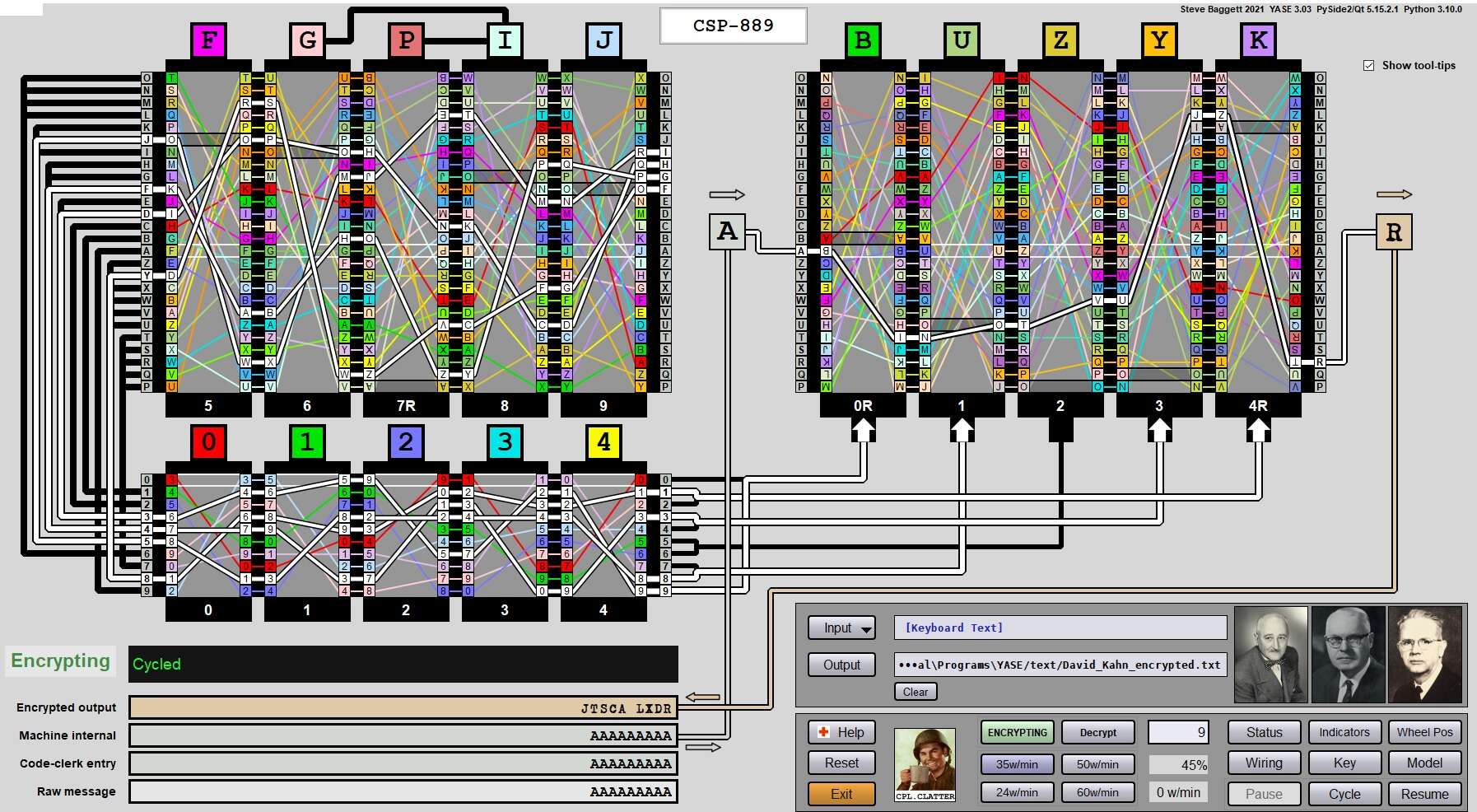
The electrical generator electrifies 4 cables: F,G,H,I (see Figures 3 & 4).
These cables energize 4 contacts located to the right of the control rotor which is in position 5, i.e. the right rotor. Then, the electrical currents generated pass through the control rotors from right to left and come out through the contacts located to the left of the first rotor, i.e. the left rotor.
The electrical circuit that connects the control rotors to the index rotors
Control rotor  	   Input index
contacts output	   rotor contacts
  A	 		9
  B 			1
  C	 		2
  D, E	 		3
  F, G, H 		4
  I, J, K 		5
  L, M, N, O	 	6
  P, Q, R, S, T 	7
  U, V, W, X, Y, Z 	8
The electrical circuit which connects the index rotors to the relays
The electrical circuit which connects the index rotors to the relays which energize the relays acting on the stepping of the encryption rotors.
Output  	Contacts
Index Rotor	Relay
  0, 9 		  1
  7, 8 		  2
  5, 6		  3
  3, 4 		  4
  2, 1		  5
The relays
If a relay is energized, the corresponding encryption rotor steps. In fact, it goes backwards: A rotor in position C, moves to position B, then to position A and then to position Z, etc. The rotor appears (seen from above) to move towards the rear of the machine. Relay 1 controls the stepping of the first rotor, relay 2 controls the stepping of the second rotor, etc.
Note: If a rotor is reversed, it appears to move forward: it moves from position A, then B, then C, etc.
The stepping of the control rotors
This progress is regular:
- The rotors in position 1 and 5 do not step.
- The rotor in position 3 steps for each encrypted or deciphered letter.
- The rotor in position 4 steps when the rotor in position 3 reaches position O.
- The rotor in position 2 steps when the rotor in position 4 reaches position O.
Counter Position of control rotors
00000 	OOOOO
00001 	ONNNO
00002 	ONMNO
00003 	ONLNO
…
00026 	ONPNO
00027 	ONONO
00028 	ONNMO
00029 	ONMMO
The CSP-2900 (differences)
The Generator and control rotors
The generator electrifies 6 wires: D, E, F, G, H, I.
The electrical circuit that connects the control rotors to the index rotors
In fact, the input of the control rotor in position 1 (left rotor) to the input of the first index rotor (left rotor).
Control rotor  	   Input index
contacts output	   rotor contacts
  A 			9
  B 			1
  C 			2
  D, E 			3
  F, G, H 		4
  I, J, K 		5
  L, M, N, O 		6
  S, T 			7
  U, V 			0
  W, X, Y, Z 		8
Note: Several control rotor outputs are not connected to the index rotors: P, Q, R.
The relays
If a relay is energized, the corresponding encryption rotor steps. If the relay 1 is energized, the rotor 1 (the one on the left) moves backwards (we go from C to B, from B to A, etc.). The same goes for relays 3 and 5. On the other hand, if relay 2 is energized, the rotor in position 2 moves forward (we go from A to B, from B to C, etc.). It is the same for relay 4 which controls rotor 4.
Note: as with the CSP-889, we have at least one rotor that steps but on the other hand all 5 rotors can step.
Benchmarks
The simulator written by R. Pekelney is special. It serves as a reference. Indeed, its author wrote it to be compatible with an authentic Sigaba which had been loaned to the museum dedicated to the USS Pampanito submarine and which he was able to inspect.
Here are the wiring used in the Pekelney simulator:
Rotor 00	YCHLQSUGBDIXNZKERPVJTAWFOM
Rotor 01	INPXBWETGUYSAOCHVLDMQKZJFR
Rotor 02	WNDRIOZPTAXHFJYQBMSVEKUCGL
Rotor 03	TZGHOBKRVUXLQDMPNFWCJYEIAS
Rotor 04	YWTAHRQJVLCEXUNGBIPZMSDFOK
Rotor 05	QSLRBTEKOGAICFWYVMHJNXZUDP
Rotor 06	CHJDQIGNBSAKVTUOXFWLEPRMZY
Rotor 07	CDFAJXTIMNBEQHSUGRYLWZKVPO
Rotor 08	XHFESZDNRBCGKQIJLTVMUOYAPW
Rotor 09	EZJQXMOGYTCSFRIUPVNADLHWBK
Rotor 10	7591482630
Rotor 20	3810592764
Rotor 30	4086153297
Rotor 40	3980526174
Rotor 50	6497135280
Remarks:
- The first rotor (00) is commented out by default. If the source code is not modified, the first rotor is replaced by direct wiring (ABCD....XYZ).
- The machine inspected by Pekelney had sanitized 26-contact rotors: their wiring corresponded to direct wiring (ABCD....XYZ). Pekelney rewired two rotors to understand how the machine worked.
Some pairs of plain text / encrypted text
First example
- Internal key
- Cypher rotors: 00 01 02 03 04
- Control rotors: 05 06 07 08 09
- Index rotors: 10 20 30 40 50
- External key
- Cypher Rotors: OOOOO
- Control rotors: OOOOO
- Index rotors: 00000 (we read on the benchmark: 10-20-30-40-50)
- Mode: Encryption
- Plain text: HELLOWORLD
- Cryptogram: FLQGF ONNOE
Second example
- Internal key: (a rotor followed by R is reversed)
- Cypher rotors: 00R 01 02 03 04R
- Control rotors: 05 06 07R 08 09
- Index rotors: 10 20 30 40 50
- External key
- Cipher rotors: ABCDE
- Control rotors: FGHIJ
- Index rotors: 01234 (we read on the benchmark: 10-21-32-43-54)
- Mode: Eencryption
- Plain text: AAAAAAAAAAAAAAAAAAA
- Cryptogram: JTSCA LXDRW OQKRX HKMVD
Third example
Note: Here, rotor 00 corresponds to the identity permutation: ABCD....XYZ. This is the case by default for the Pekelney simulator.- Internal key:
- Cypher rotors: 00 01 02 03 04
- Control rotors: 05 06 07 08 09
- Index rotors: 10 20 30 40 50
- External key
- Cypher rotors: OOOOO
- Control rotors: OOOOO
- Index rotors: 00000 (we read on the benchmark: 10-20-30-40-50
- Mode: Encryption
- Plain text: the zebre under x ray (be careful, there are spaces)
- Cryptogram: ABIEQ PEPUN YIELS OCTDH F
References
- THE ECM MARK II: DESIGN, HISTORY, AND CRYPTOLOGY, by John J. G. Savard & Richard S. Pekelney, Cryptologia, Vol. 23, No. 3, June 1999,